
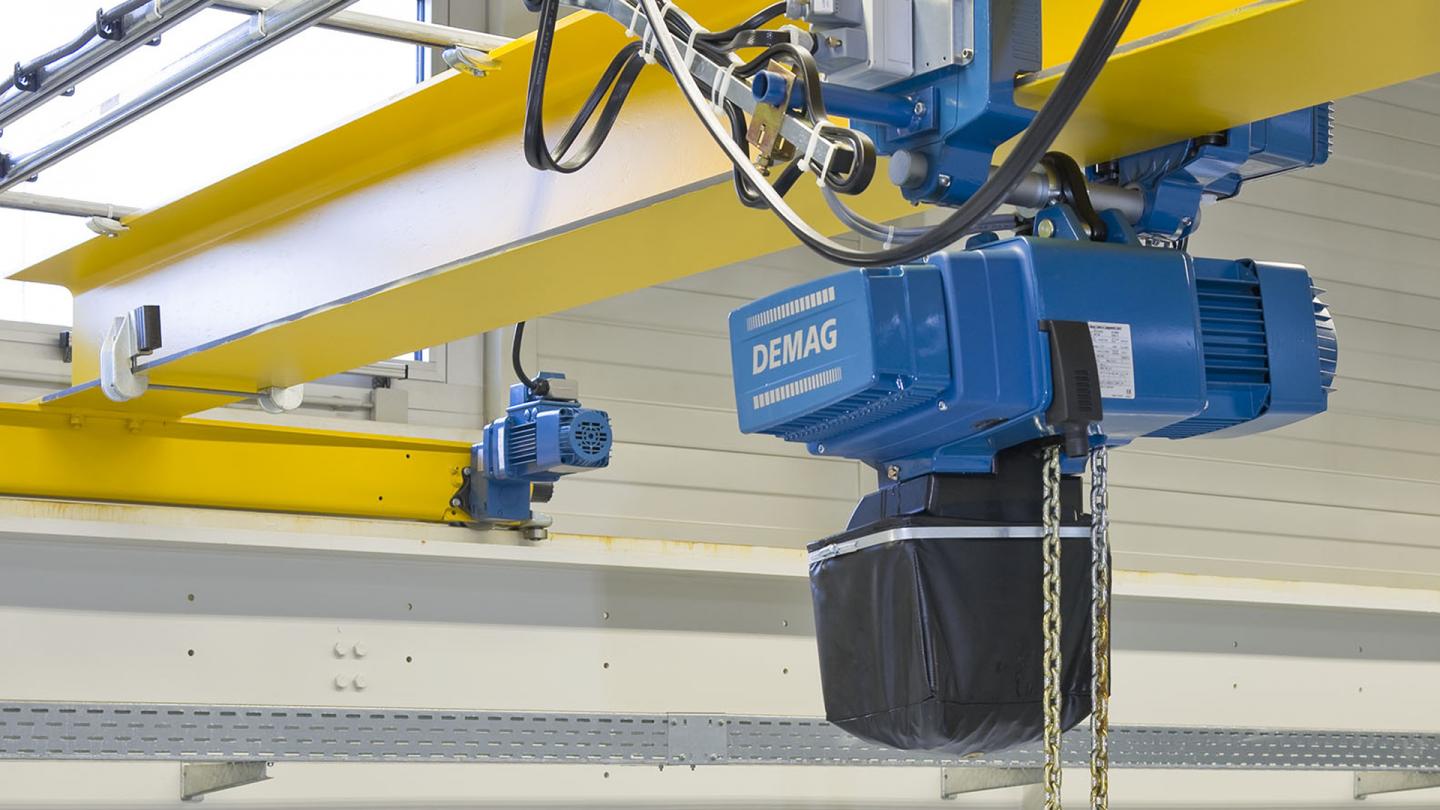
RU and CF push-travel trolleys
Our trolleys for chain hoists are a perfect match for DC chain hoists and ideal for installation on I-beam girders or on our KBK light crane system. For push travel or with electric positioning – these trolleys provide horizontal travel solutions tailored to meet specific requirements for our compact hoist units. What possibilities do they offer?
- U type trolleys for manual travel
- E type trolleys for low-sway electric travel
- Click-fit trolleys that can be clicked into position
- Smooth-running KBK trolleys as system components
- Low-headroom trolleys for optimum utilization of the available height
- Double chain hoist for mechanically synchronized lifting, e.g. for long material or large-volume components
Product information
The benefits at a glance
Click-fit trolleys
- Simple click-fit installation
- Articulated trolleys (minimum curve radius: 800 mm)
- Easily adaptable to standard-profile or parallel-flange sections
- High safety and reliability thanks to integrated drop-stop and lift-off protection
- Universal solutions for loads up to 550 kg
- Flange widths from 50 to 91 mm
U/RU push-travel trolleys
- Excellent travel characteristics
- Fast and simple installation
- Can be used on parallel and sloping flanges
- Smooth travel, low travel resistance
- Negotiate curves down to a minimum radius of 1,000 mm
- Drop stop integrated into the side cheek
- Extremely low girder wear
- Designs with polyamide or steel rollers
- Compact, state-of-the-art industrial design.
- Four sizes: U 11 up to 1,100 kg, U 22 up to 2,200 kg, U 34 up to 3,.400 kg, RU 56 up to 5,600 kg
E 11 to E 34 electric travel drives
- Smooth starting and braking
- Low-sway load handling
- Fast installation and commissioning
- Designed for operation with DC-Pro chain hoists
- Control via DSE 10-C/DSE 10-CS control pendants
- Fast availability thanks to plug-&-drive: plug-in connection to DC-Pro chain hoists
- Simple installation of the control pendant for long/cross travel
- Optional accessory: cross-type limit switches for fast-to-slow and final limit-switch cut-off
KBK trolleys
- E 22 fitted as standard with RF 125 friction-wheel travel drive for use with KBK light crane system
- Particularly short approach dimensions for vertical mounting arrangement
Technical data
Selection table
|
Max. dis- placeable weight incl. |
Travel drive |
Travel speed at 50/60 Hz | Possible trolleys |
Max. Weight [kg] |
|||
| Steps | Stepless | ||||||
| Vrated at full load [m/min] |
Vmax at partial load1) [m/min] |
V at full load [m/min] |
V at partial load [m/min] |
||||
| 1,100 | E 11 | 24/6 | 30/7.5 | 1.2-24 | 1.5-30 | U 11 | 4 |
| 2,200 | E 22-C | 24/6 | 30/7.5 | 1.2-24 | 1.5-30 | U 22 U 34 |
5 |
| 2,200 | E 22-C | 27/7 | 33/8 | 1.4-27 | 1.65-33 | RF 125 | 5 |
| 3,400 | E 34 | 14/3.5 | – | 0.7-14 | – | U 34 | 5 |
| 5,600 | EU 56 | 12/4 24/6 40/10 | – | On application | RU 56 | 8.8 |
1) Possible by programming other parameters
2) Max. displaceable weight/max. gradient 1% > 1% on request
Curve radii for trolleys
| Trolleys | Load capacity |
Runway girder | Travel wheel material | |||
| Push travel | Electric travel | |||||
| [kg] | Flange width [mm] | Rmin | Flange width [mm] | Rmin | ||
| CF 5 | 550 | 50-91 | 800 | – | – | Plastic |
| U 11 DC EU 11 DC |
1,100 | 58-310 | 1,000 | 58-310 | 2,000 | Plastic 2) |
| U 22 DC EU 22 DC |
2,200 | 74-2004) | 2,000 | 82-2004) | 3,000 | Spheroidal-graphite cast iron 3) |
| U 34 DC EU 34 DC |
2,200 3,400 |
201-3101) 74-3101) |
2,000 | 82-3101) | 3,000 | Spheroidal-graphite cast iron |
| RU 56 DC EU 56 DC |
5,600 | 98-310 | 2,0005) | 98-310 | 2,5005) | Spheroidal-graphite cast iron |
1) Flange width for DC 16/25 = 90-310 mm
2) Steel travel wheels optional
3) Plastic travel wheels on request
4) Flange width for DC 16/25 = 90-200 mm
5) From flange width 106 mm
The specified curve radii apply for normal applications. Contact the manufacturer or his representative for frequent curve travel operation (e.g. automatic installations).
